PV Transformers vs. Conventional Transformers:
Core Differences & Design Features
A practical reference for EPC contractors and grid integration engineers on why solar step-up transformers demand a fundamentally different design — and what happens when you spec the wrong unit.
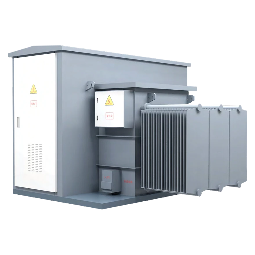
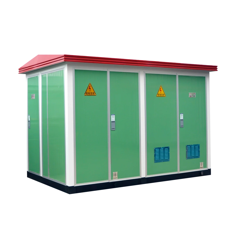
Haocheng New Energy Series compact substation — engineered for wind and solar grid integration in harsh outdoor environments.
Load Profile: Why Solar Duty Is a Different Physical Reality
Conventional distribution transformers serve commercial, industrial, and residential loads that follow predictable daily curves. The transformer settles into a stable thermal equilibrium and holds there. A photovoltaic step-up transformer operates under an entirely different physics.
Daily Thermal Cycling
Solar irradiance drives the transformer from zero to full load within hours every morning, then back to zero each night. This daily thermal expansion–contraction cycle creates cumulative mechanical fatigue in windings and accelerates insulation aging over the plant's 25-year lifespan.
No-Load Loss During Idle Hours
During nighttime non-generation periods, the transformer remains energized by the grid, continuously incurring core (no-load) losses. For a 100 MVA step-up unit, unoptimized core losses can translate into tens of thousands of dollars in avoidable annual energy cost.
Reverse Power Flow
Power moves from the low-voltage inverter output up into the high-voltage grid — the opposite direction from conventional distribution. This affects impedance matching, protection relay settings, and harmonic propagation paths throughout the system.
This is why minimizing no-load (core) losses carries far greater weight in PV transformer design than it does for conventional units, where load-loss optimization typically dominates the efficiency calculation.
Harmonic Stress: The Hidden Threat Inside Every Solar Transformer
Unlike conventional transformers that handle clean 50/60 Hz sinusoidal waveforms, PV transformers connect directly to solid-state inverters. The high-frequency switching topology of these devices injects substantial harmonic currents into the low-voltage windings. Two failure mechanisms follow.
Skin Effect and Proximity Effect
High-order harmonic currents concentrate toward the outer surface of conductors rather than distributing uniformly across the cross-section. This effectively increases resistance, raises copper losses, and generates localized heating that standard thermal models may not flag until insulation is already compromised.
Eddy Current and Stray Loss Amplification
Eddy current losses scale approximately with the square of frequency. An 11th-order harmonic (550 Hz on a 50 Hz system) theoretically produces 121 times the eddy current loss of the fundamental — concentrated in the core steel and structural tank components as invisible hotspots.
A PV transformer is not a conventional transformer running in reverse. Specifying a standard distribution unit for a solar step-up application and expecting acceptable performance over a 25-year asset life is an engineering error, not a cost optimization.
K-Factor Rating: The Harmonic Design Standard
The K-Factor system quantifies the additional thermal burden that harmonic loading imposes on a transformer. K-1 represents a pure sinusoidal load. Central inverter applications in utility-scale PV plants commonly require K-4 through K-13 — which must be calculated from actual or simulated harmonic spectra, not assumed from equipment type alone.
Engineering countermeasures built into correctly rated PV transformers include:
- Continuously transposed conductors (CTC) or multi-strand parallel windings to suppress eddy current losses
- Oversized neutral conductors to carry triplen harmonic currents without thermal runaway
- Reduced core flux density to prevent magnetic saturation caused by DC bias and harmonic distortion from the inverter stage
Split-Winding Configuration: Standard Architecture for Utility-Scale Plants
In utility-scale solar installations, the step-up transformer commonly adopts a dual-split low-voltage winding design: one HV winding magnetically coupled to two independent, electrically isolated LV windings, each feeding a separate central inverter unit.
The critical engineering value is high decoupling impedance between the two LV windings. When a fault occurs on one inverter segment, the elevated inter-winding impedance contains the short-circuit current within that segment. The adjacent inverter continues generating without interruption — directly protecting revenue-generating availability during fault events.
This architecture represents a deliberate departure from the standard dual-winding convention that governs conventional distribution transformer design.
Technical Comparison at a Glance
The following table summarizes the principal design and operational differences between PV step-up transformers and conventional distribution transformers.
| Parameter | PV Step-Up Transformer | Conventional Distribution Transformer |
|---|---|---|
| Power Flow Direction | Step-up; reverse / bidirectional — inverter to grid | Step-down; unidirectional — grid to load |
| Load Characteristics | Intermittent, cyclic, weather-dependent with steep daily ramp rates | Continuous and relatively stable, follows consumer demand profiles |
| Winding Configuration | Dual-split or multi-split LV windings with high decoupling impedance | Standard single-primary / single-secondary, or conventional 3-winding |
| Harmonic Rating (K-Factor) | K-4 to K-13+ required; winding reinforced for high-order harmonics | K-1 sinusoidal rating; low tolerance for harmonic overheating |
| Loss Optimization Priority | No-load (core) losses — transformer idles energized nightly | Balanced optimization of both load and no-load losses |
| Insulation Design | Enhanced dV/dt withstand; rated for inverter-generated transient spikes | Standard dielectric strength for grid-frequency voltage stress |
| Installation Environment | Harsh outdoor: desert, salt-mist coastal, high-altitude sites | Indoor electrical rooms, urban basements, standard pole / ground pads |
| Enclosure / Integration | Compact (box-type) substation, pad-mounted or integrated skid | Open-frame, pole-mounted, or standard substation enclosure |
Installation Environment and Enclosure Requirements
Conventional distribution transformers operate in relatively controlled environments. PV transformers are routinely deployed across some of the most punishing terrain on the planet: Gobi Desert sites with 40°C+ daily temperature swings, coastal solar farms with sustained salt-fog exposure, and high-altitude installations where reduced air density degrades cooling efficiency.
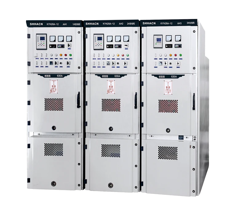
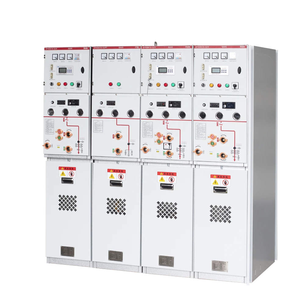
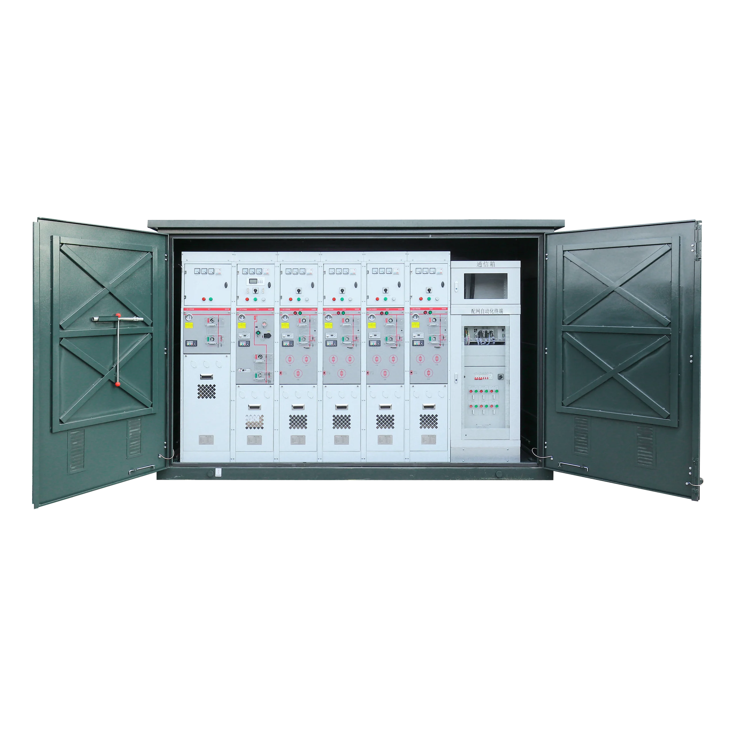
At the utility scale, PV step-up transformers are typically integrated into compact pad-mounted substations (box-type or American-style), which compress the MV switchgear, transformer, and LV connection into a single factory-tested enclosure. This shortens on-site commissioning time but places stringent demands on thermal management layout and internal clearances.
For distributed rooftop and urban edge installations, dry-type or cast-resin transformers eliminate dielectric fluid entirely, removing both the fire risk and the environmental liability associated with insulating oil in densely occupied settings.
Safety and Compliance: Four Engineering Baselines
Per IEC 61936, IEEE C57, and applicable national grid codes, the following safeguards govern PV transformer deployment regardless of project scale.
EMF Containment
A fully sealed and grounded steel tank reduces external ELF electromagnetic field levels to well below ICNIRP public exposure thresholds — critical for projects near commercial or mixed-use zones.
Acoustic Noise Control
Core magnetostriction noise peaks during peak solar hours when load and cooling fans are both at maximum. Step-lap skewed core joints and vibration-isolation base pads are standard mitigation for projects adjacent to residential areas.
Oil Containment
Unmanned solar sites require hermetically sealed corrugated tanks or conservator systems with continuous oil-level monitoring accessible via SCADA, preventing undetected leaks in remote environments.
Physical Isolation
Compliant safety clearances attenuate both residual EMF and audible noise to background levels while tamper-resistant locking mechanisms prevent unauthorized access — a standard regulatory checkpoint for projects near public facilities.
Haocheng New Energy Series
PV step-up transformers and compact substations engineered for solar and wind grid integration — oil-immersed and dry-type configurations, rated for desert, coastal, and high-altitude deployment.