Data Center Power Transformers: Tier III & Tier IV Reliability
Operators talk about UPS runtime and generator redundancy, but the step-down transformers between the utility service and the critical bus are what actually decide whether a Tier rating survives contact with reality.
A Tier IV facility keeps A and B transformer paths physically separated and simultaneously active, all the way to a dual-corded load.
A facility can have flawless UPS topology and still fail concurrent maintainability testing because someone specified a single dry-type unit feeding two "independent" switchgear lineups. Transformer selection, sizing, and physical arrangement are structural decisions — poured into concrete long before the first server ships. This is what actually changes in the electrical room as a facility moves from Tier III to Tier IV.
Where the Two Tiers Actually Diverge
The facility is only as reliable as its weakest link. A building with a fault-tolerant cooling plant and a single utility transformer is rated on the transformer.
Six Decisions That Determine the Rating
These are worked through in the order they tend to surface during design — starting with what the standard requires, then what the transformer has to survive, then how the program keeps the rating true after commissioning.
Tier III requires that every capacity component and distribution path can be taken offline for planned maintenance without interrupting IT load — N+1 at minimum, with an alternate path available while the primary is serviced. Tier IV goes further: the facility must absorb an unplanned single-component failure, not just a scheduled outage, without dropping load.
For transformers, an N+1 bank behind a shared busway satisfies planned-maintenance testing but can still fail through a common-mode fault. Tier IV assessors look for real physical separation — separate vaults, independent conduit runs, no shared neutral or ground between the A and B systems.
Tier III typically runs one active path with a redundant standby, or N+1 units on a shared bus through transfer arrangements. Tier IV requires two complete, independently sized systems — each rated to carry the full IT load alone — kept active simultaneously rather than held in standby. Some owners add 2N+1 so a maintenance window on one leg doesn't strip that leg of redundancy.
This changes capacity planning beyond steady-state load: each path now has to independently absorb transfer surges and inrush from the other side during failover without nuisance-tripping upstream protection.
Cast-coil and VPI dry-type units, built to IEEE C57.12.01 and tested per C57.12.90, dominate indoor step-down duty in the 500–2,500 kVA range because they avoid the fire suppression and containment provisions NEC Article 450 imposes on indoor liquid-filled units.
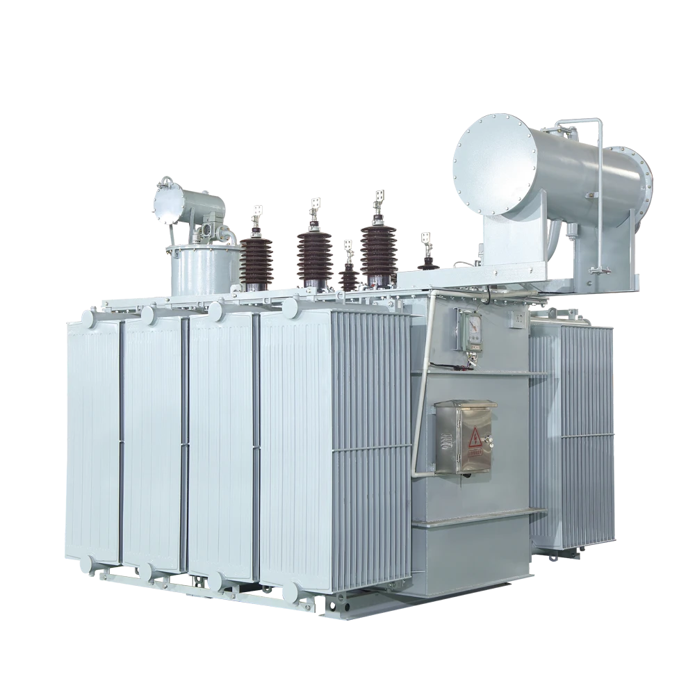
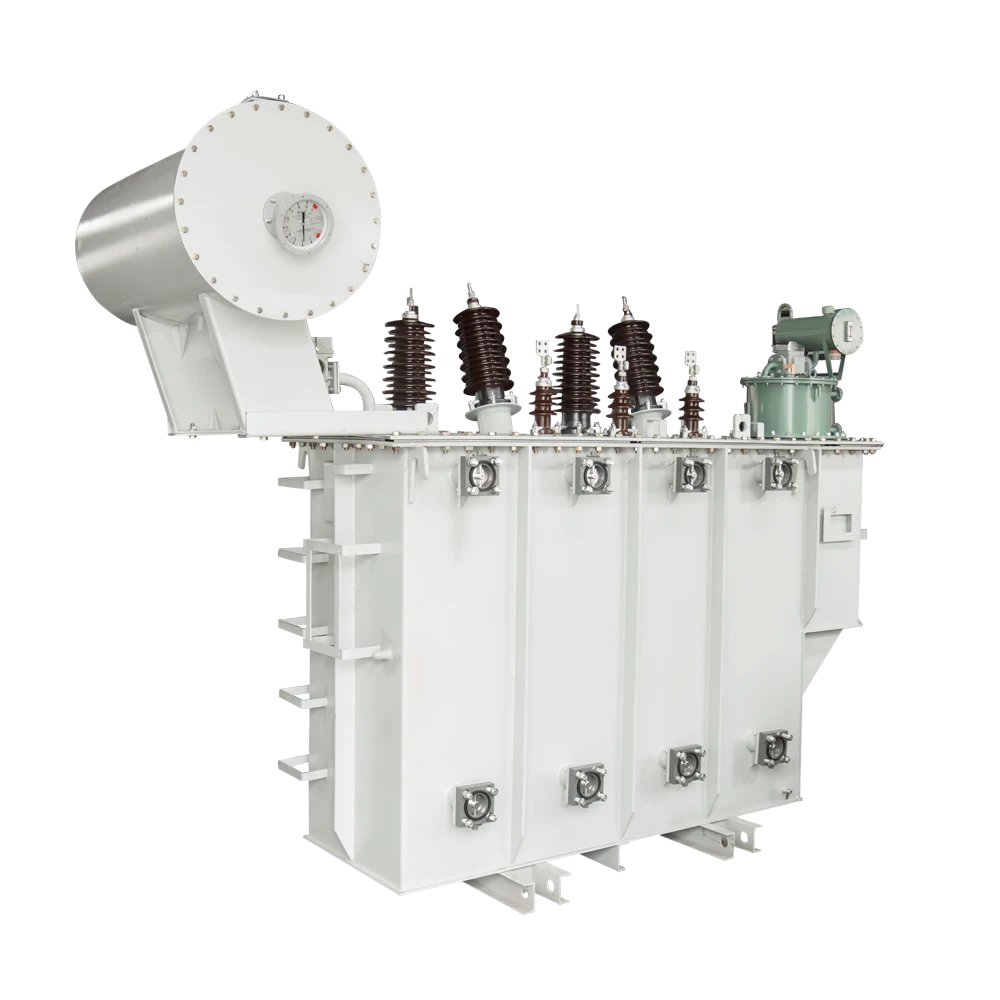
Liquid-filled transformers, increasingly with natural or synthetic ester fluids for their higher fire point, still show up at the utility-to-medium-voltage stage, particularly on campus-style sites where the unit sits outdoors in a dedicated substation yard.
Server power supplies, VFDs, and UPS rectifier stages all inject harmonic current that raises eddy-current and stray losses well above what nameplate kVA implies. A unit loaded to rated kVA under a distorted waveform runs hotter than the same unit under a clean sine wave — a common root cause of premature insulation aging.
K-factor rated transformers, built to UL 1561 / ANSI C57.110 guidance, add winding strand transposition and eddy-current withstand specifically to carry nonlinear load at full rated kVA. A conservative margin on a general-purpose unit is not a substitute.
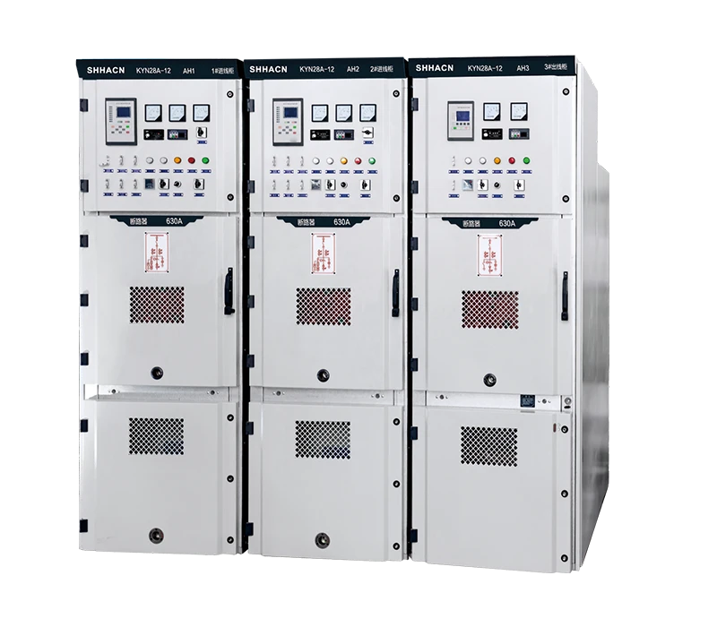
Assessors verify isolation points — primary and secondary disconnects, bypass arrangements, grounding provisions — at every unit, and confirm the protective coordination study accounts for a transformer being removed from service, not just a fault condition.
A common failure: dual-corded IT equipment feeding two "redundant" PDUs that both trace back to the same upstream transformer. That unit is a single point of failure the moment it needs maintenance.
Factory acceptance testing — turns ratio, winding resistance, insulation resistance, induced/applied voltage withstand per IEEE C57.12.90 — is repeated in the field to catch shipping damage. Doble power-factor testing and infrared thermography at scheduled intervals catch developing winding and connection problems before they become an unplanned outage.
For liquid-filled units, recurring dissolved gas analysis remains the best early-warning tool — specific gas ratios reveal thermal faults and partial discharge well before a trip. Skipping DGA quietly downgrades fault tolerance regardless of what the design documents say.
Tier III vs. Tier IV, Quick Reference
What actually changes in the electrical distribution chain between the two ratings.
| Attribute | Tier III | Tier IV |
|---|---|---|
| Redundancy model | N+1, single active path | 2N or 2N+1, dual active paths |
| Failure tolerance | Planned maintenance only | Planned and unplanned single failures |
| Physical separation | Not required between redundant units | Independent, physically isolated systems |
| Design availability | 99.982% (~1.6 hrs/yr downtime) | 99.995% (~26 min/yr downtime) |
| Typical adopter | Enterprise colocation, general SaaS | Banking, payments, government, regulated healthcare |
Figures reflect Uptime Institute design-target norms. Confirm against current Tier Standard documentation and a licensed engineer's coordination study before finalizing a design.
Matching the Tier to the Workload
Enterprise Colocation
Tier III is the sweet spot — concurrently maintainable N+1 transformer redundancy at capital costs that scale sensibly for multi-tenant space.
Banking & Payments
Tier IV's fault-tolerant 2N transformer topology earns its premium where even a single unplanned failure isn't tolerable.
Government & Healthcare
Regulatory and continuity-of-service requirements typically push these workloads toward Tier IV physical separation standards.
Hyperscale Cloud
Many operators stay at Tier III per site and achieve resilience across multiple availability zones instead of doubling every substation.
The Transformer Vault Is Usually Built Before Certification Begins
Harmonic content, future capacity headroom, and the physical separation required to make redundancy real under fault conditions all have to be decided at the one-line diagram stage — neither tier forgives a transformer specification that ignores the actual load it will carry.