Transformer Sizing for PV and BESS: What Trips People Up
Sizing a transformer for solar or storage is never just picking a kVA number off an inverter datasheet. The load basis, the harmonics, the cooling class, and the grounding scheme all decide whether the unit runs cool for 30 years or gets replaced at year ten.
A PV or BESS step-up transformer sees a very different duty cycle than a standard distribution unit — sizing has to reflect that.
Transformer selection is one of those areas on solar and storage projects where a lot of people get burned early on. There isn't a lot of plain-language material out there on this, since most vendor datasheets assume the reader already knows what they're doing. The sections below cover what actually matters — from load basis and harmonics through grounding, cooling, and the mistakes that keep showing up on real projects.
Los números que suelen decidirlo
The transformer that fails early was almost never undersized on paper. It was sized to the wrong load basis in the first place.
The Factors That Actually Matter
These are worked through roughly in the order they tend to come up during design — starting with what defines the load, then what the transformer has to survive, then what protects it long-term.
Sizing off the sum of inverter nameplate ratings overshoots the real requirement, since DC/AC ratios of 1.2 or higher mean the inverter rarely pushes full nameplate outside a handful of clipping hours. Realistic continuous AC output — based on site irradiance data, plus whatever power factor the utility requires — is the number that matters.
BESS is different again, since power flows both directions and, depending on the application (arbitrage, frequency regulation, peak shaving), the unit can sit near rated power far more often than a PV plant ever would.
Inverters and PCS units are switching devices, and harmonic current still flows into the transformer regardless of how clean the filtering looks on paper — driving extra eddy current and stray losses that a plain 60 Hz sine-wave design never accounted for. Actual THD data at partial load, not just rated output, matters more than most vendor sheets suggest.
A K-factor rated unit, or a derating calculated per IEEE C57.110, is the difference between normal insulation life and replacing it ten years early.
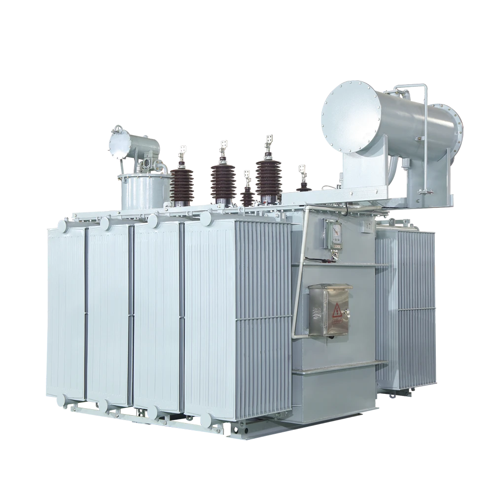
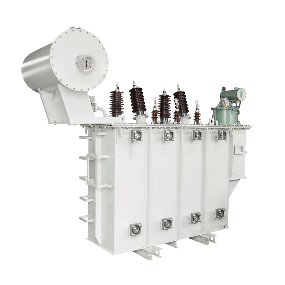
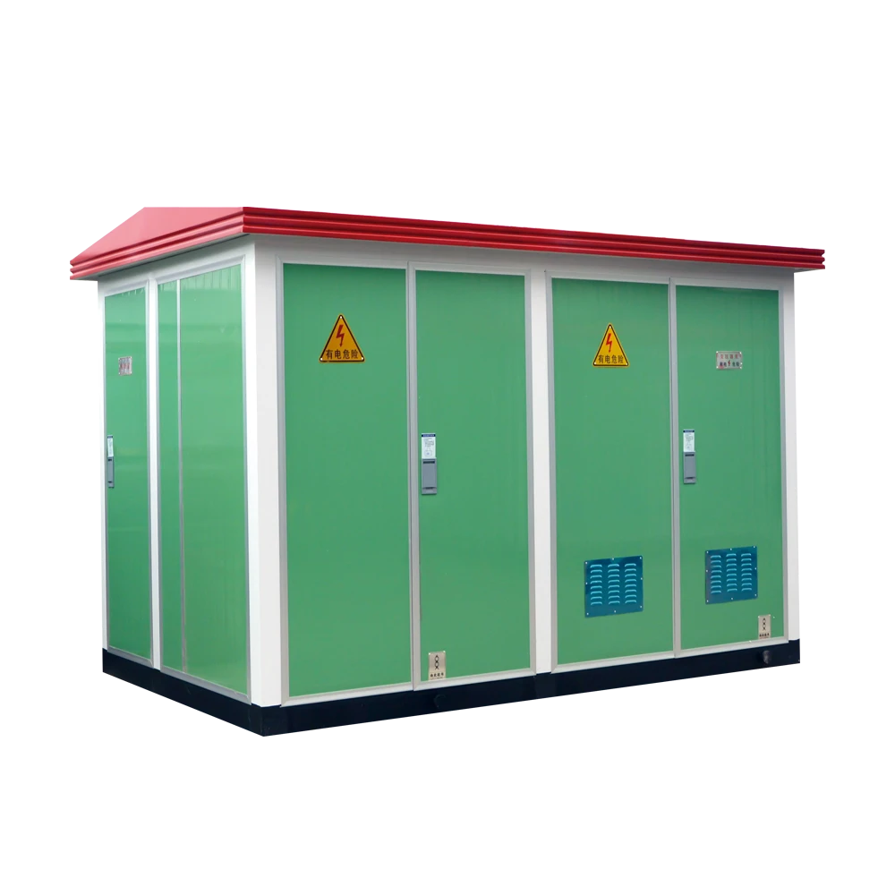
Most ground-mount utility-scale sites still run oil-filled, pad-mounted units — cheaper per kVA, better overload handling. BESS sites increasingly push toward dry-type or ester-fluid transformers even at a cost premium, mainly because it simplifies the fire protection conversation with the AHJ when the unit sits next to battery enclosures. Rooftop and carport PV is almost always dry-type given the installation location.
On sites that run hot, or where the load profile sits near rated output often, ONAN/ONAF instead of plain ONAN is usually worth the extra cost — the fan stage buys roughly 15–30% more capacity for a small fraction of total transformer cost. Ambient temperature and altitude correction factors are worth double-checking too; this gets missed constantly on desert and high-elevation sites.
Impedance should be worked out with a protection engineer before finalizing anything — too low and downstream fault currents get nasty, too high and voltage regulation problems show up, which matters more on PV because of cloud transients and on BESS because of fast power swings during cycling. Vector group matters too: Dyn11 (or Dyn1, region dependent) is the usual choice for step-up transformers, since it provides a grounded reference point that most inverters and PCS units need on their side.
Unless there's a specific requirement for active voltage regulation as a grid service, an on-load tap changer usually isn't worth the added cost and maintenance burden. A de-energized tap changer, set once at commissioning based on measured site voltage, is sufficient for the large majority of PV and BESS installations.
Nameplate ratings shouldn't just be added together. The actual coincident power flow needs modeling, since PV generation and BESS charge/discharge rarely peak in the same direction at the same time — and the real ceiling is usually the POI interconnection limit, not the sum of equipment nameplates.
A loss evaluation — no-load losses and load losses, capitalized — is worth requesting before picking a transformer on price alone. Over a 20–30 year project life, losses can outweigh the purchase price difference between two otherwise similar units. Utilities usually have their own loss evaluation formula available on request.
Common Mistakes, Quick Reference
The same handful of errors keep showing up across otherwise well-engineered projects.
| Mistake | Consequence | Fix |
|---|---|---|
| Sizing off DC nameplate | Oversized, more expensive transformer for the actual AC duty | Size to realistic continuous AC output plus POI power factor |
| Skipping harmonic derating | Unit runs hotter than nameplate suggests; early insulation loss | Get vendor THD data at partial load; apply C57.110 derating or spec K-factor |
| Ignoring altitude / ambient correction | Transformer derated more than planned on desert or high-elevation sites | Check correction factors against actual site conditions before finalizing |
| Adding PV + BESS nameplates | Oversized shared transformer relative to real coincident load | Model coincident power flow against the POI interconnection limit |
| Grounding/vector group decided late | Rework at commissioning; nuisance tripping or undetected ground faults | Lock in with protection settings early in design, not at commissioning |
Figures throughout are directional industry norms. Confirm exact ratings, derating factors, and grounding requirements against the applicable interconnection utility spec and local code before finalizing a design.
Where to Start on a Given Project
PV-Only Plant
Start with realistic AC output from irradiance data and POI power factor, then layer in harmonic derating from actual inverter THD figures.
BESS Plant
Model the duty cycle for the specific use case — frequency regulation runs a transformer far harder than occasional peak shaving.
Hybrid PV + BESS
Model coincident load against the POI limit rather than adding nameplates — this is where oversizing most often creeps in.
Hot or High-Elevation Sites
Confirm ambient and altitude correction factors early, and weigh ONAF against plain ONAN before locking in a cooling class.
Built for PV, BESS, and Distribution Duty
Oil-immersed, dry-type, and amorphous alloy core options engineered for harmonic-rich, cyclic, and high-utilization loads typical of solar and storage plants.