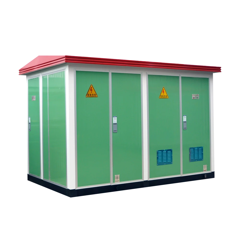
Transformer Abnormal Noise & Excessive Vibration:
4-Step Troubleshooting from the Field
A structured diagnostic protocol for O&M personnel — from acoustic triage and thermal imaging to instrumented fault localization and safe return-to-service. Written by engineers who commission and maintain power transformers in demanding grid environments worldwide.
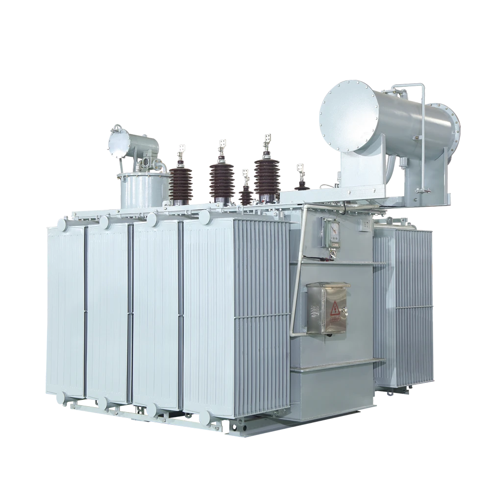
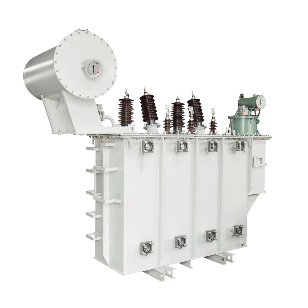
Haocheng low-loss OLTC transformer series — built for long-cycle reliability in utility and industrial grid applications across Africa, Central Asia, the Middle East, and Southeast Asia.
Every experienced O&M engineer knows the feeling: you're on a routine walkthrough and something just sounds off. Not dramatically wrong — a subtle shift in pitch, or a vibration pattern that wasn't there last week. That instinct is worth listening to. A healthy transformer produces a steady 100–120 Hz hum from magnetostriction in the core laminations. The moment that sound changes — irregular, intermittent, or sharper — your diagnostic clock starts.
Why Abnormal Noise and Vibration Demand Immediate Attention
Transformer failures are rarely instantaneous. They announce themselves through sound, heat, and vibration long before a catastrophic event. Insulation degradation, inter-turn winding faults, and core loosening all produce detectable symptoms if you know where to look and listen.
Operators who establish baseline acoustic and vibration profiles for each unit consistently catch faults at the remediation stage — before protection trips and forced outages. Our field data across international utility accounts shows that faults caught at the acoustic anomaly stage typically cost 10–30% of the remediation cost of failures detected only after relay operation or visible physical damage.
A transformer doesn't fail silently. The question is whether your team is listening before the protection relay answers that question for you.
Acoustic & Visual Diagnosis: Mapping 4 Common Fault Categories
Before reaching for instruments, an experienced technician can narrow the fault category considerably using a structured "listen and look" approach. Think of this as triage — narrowing the search space before committing to instrumented diagnostics.
Electromagnetic Faults
Most commonly encountered. Produces buzzing or hissing layered over the baseline hum, often with a harmonic character. DC bias, core lamination loosening, and inverter-sourced harmonics (VFDs, UPS, rectifiers) are the primary drivers.
Mechanical Faults
Usually irregular and metallic, or positional — louder from one face of the tank than another. Loose clamping bolts, core tie rods, winding axial displacement, and tank wall resonance are the usual suspects.
Cooling System Faults
Frequently misidentified. Blocked radiator fins, oil pump cavitation, and fan bearing wear all produce distinctive acoustic signatures — and all feed thermal imbalance back into the core, compounding the noise problem.
Environmental & Installation Issues
Often the last category checked, but the most fixable. Foundation settling, loose anchor bolts, structural resonance from adjacent steel platforms, and nearby vibrating machinery can all amplify an otherwise normal operating unit to alarming levels.
Electromagnetic Fault Details
DC bias from geomagnetic disturbances or half-wave rectifier loads causes the core to operate asymmetrically, increasing vibration amplitude at the fundamental frequency and introducing odd-order harmonics — producing a pronounced buzzing that correlates with load changes. Core lamination loosening typically manifests as rattling or chattering at no-load or light load, intensifying during energization transients. High-voltage harmonics from nonlinear loads amplify magnetostriction at specific frequencies.
Measure load current waveform quality with a clamp meter. Total harmonic distortion (THD) exceeding 5% alongside abnormal noise strongly suggests an electromagnetic origin.
Mechanical Fault Details
Loose clamping bolts or core tie rods produce intermittent knocking correlated with thermal expansion–contraction cycles. Winding axial displacement produces a deeper, rhythmic thumping that persists across load levels. Tank wall resonance is common in oil-immersed units with loose reinforcement plates.
Use a calibrated vibration analyzer at multiple points on the tank exterior. Amplitude spikes at specific locations indicate localized mechanical loosening rather than a distributed electromagnetic source.
Cooling System Fault Details
Blocked radiator fins cause thermal imbalance that feeds back into increased magnetostriction and vibration. Pump cavitation produces a churning or gurgling sound from the lower tank area. Fan motor bearing wear is easy to misidentify as a winding fault — isolate by briefly running the unit with forced cooling disabled (where operationally safe) and noting whether the noise signature changes.
Thermal image the radiator panels under rated load. Blocked sections appear as cold zones against an otherwise warm radiator array — a clear, unambiguous indicator of restricted oil flow.
Environmental & Installation Fault Details
Foundation settling or loose anchor bolts can amplify normal operating vibration to alarming levels — the transformer itself may be entirely within spec. Resonant frequency coupling between the transformer and nearby steel structures is particularly common on mezzanine-mounted installations. Always check whether the noise correlates with adjacent machinery start/stop cycles before concluding the transformer is at fault.
Place a vibration sensor on the foundation pad and compare readings to the tank body. Significantly higher foundation readings indicate a structural amplification problem, not an electrical fault.
The Standardized 4-Step Troubleshooting Workflow
The governing principle for all transformer field work: safety first, external before internal, simple before complex. No diagnostic finding justifies working inside an energized transformer.
- Verify load stability on the control panel — confirm no active overcurrent, overvoltage, or differential protection alarms
- Assemble diagnostic kit: insulated acoustic stethoscope or listening rod (minimum 20 kV rating for HV proximity), calibrated thermal imager, torque wrench set, vibration analyzer
- Don rated PPE: insulated gloves appropriate to the operating voltage class, safety goggles, arc-flash-rated face shield for any work near MV/HV terminations
- Brief the team on the LOTO procedure that will apply if Steps 3 or 4 require de-energization
Transformer substations are among the highest-consequence electrical environments in routine O&M work. Shortcuts taken here have ended careers and lives. Do not compress this step under schedule pressure.
Work methodically around the energized unit before forming any conclusions. This step resolves a significant proportion of fault categories without requiring de-energization.
- Walk the perimeter — listen for directional noise differences; note which face of the tank sounds loudest
- Check oil level and color — low oil in ONAN/ONAF units correlates with thermal issues; darkened or cloudy oil may indicate internal arcing
- Inspect bushing surfaces — corona discharge produces a hissing, sizzling sound with a distinct ozone odor; it is sometimes misidentified as internal noise
- Examine the radiator array and fans — look for blocked fins, damaged fan blades, oil leak trails on radiator tubes
- Check all visible external fasteners — tank cover bolts, radiator mounting hardware, cable tray supports
- Photograph every anomaly — timestamped photos become part of the fault record and support warranty or insurance claims if escalation is needed
If Step 2 has not resolved the fault category, move to instrumented diagnostics. These tests can mostly be performed with the unit energized; Step 3b and beyond require coordination with operations.
- Three-phase voltage and current balance — Un desequilibrio superior al 5 % en los bujes de baja tensión justifica una investigación inmediata de la carga.
- Core earth current measurement — use a clamp meter on the core ground lead. Elevated earth current indicates multi-point grounding: circulating currents, accelerated core heating. IEEE C57.110 and IEC 60076-1 both classify this as a maintenance priority requiring action
- Vibration signature analysis — record acceleration spectra at four tank points (front, rear, and both sides at mid-height); compare against the baseline profile. New peaks at non-fundamental harmonics point toward specific fault types
- DGA sampling for oil-immersed units — if acoustic and thermal findings suggest internal arcing or overheating, schedule dissolved gas analysis. Key fault gases (hydrogen, acetylene, ethylene) allow severity classification per IEC 60599 action levels
- Winding deformation assessment — where serious mechanical fault is suspected and cannot be confirmed externally, a planned outage must be arranged for untanking and physical inspection of winding geometry
Not all faults are equal in urgency or corrective complexity. The remediation path must match the fault severity.
For minor, confirmed faults (loose external hardware, blocked radiator, fan bearing replacement): perform on-site rectification with the unit de-energized and grounded; re-energize under observation; monitor acoustic and thermal profile for the first 30 minutes; document the fault, root cause, and corrective action in the equipment health log.
For significant faults (winding deformation, confirmed core fault, insulation resistance below minimum thresholds): immediately isolate and de-energize. Do not attempt forced re-energization under any circumstances. Before recommissioning, complete the full pre-service test suite — insulation resistance (IR), polarization index (PI), winding DC resistance, power factor/tan delta, and turns ratio. For units with DGA findings above IEC 60599 action thresholds, consult the manufacturer before returning to service.
Fault Reference: Noise Character vs. Probable Cause
Use this table as a rapid reference during field assessment. Sound character alone does not confirm a fault — use it to prioritize which diagnostic path to pursue first.
| Noise / Vibration Character | Probable Fault Category | First Diagnostic Action |
|---|---|---|
| Intensified, steady buzzing correlated with load changes | DC bias or harmonic distortion from nonlinear load | Measure load current THD; check for rectifier or VFD loads upstream |
| Rattling or chattering at no-load or light load | Core lamination loosening; reduced clamping force | Check core clamping bolt torque; schedule untanking inspection if confirmed |
| Intermittent metallic knocking; load-cycle correlated | Loose external or internal mechanical fasteners | External: torque check all visible hardware. Internal: requires de-energization |
| Deep, rhythmic thumping independent of load level | Winding loosening or axial displacement (serious) | Immediately schedule vibration profiling and power-off winding inspection |
| Churning or gurgling from lower tank area | Oil pump cavitation or low oil level | Check oil level; inspect pump inlet screen for blockage |
| High-pitched whine from cooling zone | Fan motor bearing wear | Temporarily disable forced cooling (where safe); observe whether noise source isolates |
| Hissing with ozone odor at bushing surfaces | Corona discharge on bushing or external insulation | Inspect bushing surface and connections; schedule HV withstand test |
| Vibration significantly higher at foundation than tank | Foundation settling or structural resonance coupling | Check anchor bolt torque and isolation pad condition; assess adjacent equipment |
Critical O&M Observations: What Experience Teaches
A few things the field consistently confirms that formal training sometimes doesn't emphasize:
Louder Is Not Always Worse
Newly commissioned units, transformers recently re-energized after outages, and high-capacity units near rated load all operate at higher acoustic levels. The diagnostic question is always: is the sound uniform and stable, or erratic and changing? A steady elevated hum is usually benign. A subtle, irregular anomaly at low amplitude is often the more serious signal.
Seasonal Changes Shift Baseline Behavior
Ambient temperature changes affect oil viscosity, core lamination thermal expansion, and mounting hardware elasticity. A loose bolt that holds through summer may begin rattling in the first cold snap. Establish inspection benchmarks in both warm and cold conditions — and note both in the equipment health log.
Proactive Beats Reactive on Every Metric
Monthly acoustic and thermal inspections, quarterly vibration profiling, and annual DGA testing are not overhead — they're insurance that pays for itself by orders of magnitude. The window between detectable anomaly and forced outage is where maintenance cost is determined.
LOTO Is Not a Formality
Any inspection of internal components must follow complete de-energization, verified grounding, and lockout/tagout tagging per applicable national safety regulations and IEC 60900. This procedure exists because violations of it are fatal. There are no acceptable shortcuts.
Haocheng Transformer Series
Oil-immersed and dry-type distribution and power transformers, low-loss OLTC units, and turnkey substation packages — built for demanding utility and industrial applications across Africa, Central Asia, the Middle East, and Southeast Asia.